Here's some stuff I learned during my 40k timing belt change.
I disconnected the battery ground cable and had it off for ten days or so while I made the tools and changed the belt. I didn't loose any computer or radio settings at all. It was just like I had never disconnected it at all.
Even though Bentley seems to think that measuring the width of the belt will tell something about the condition it's in, I found the width to vary a great deal from one spot to another. My old belt measured from .970" to .992". The new belt having never been run measured from .978" to .994". These represent the greatest range I could find on either belt using multiple random samples and then chasing a wide or narrow spot to the extreme when I found it.
The reddish dust I found inside the timing belt cover seems to be worn fiber from the face of the teeth, although from the looks of the belt it could have gone a lot farther than 40k.
Leaving out the windshield washer reservoir till after the timing is set would give a lot more room.
Contrary to what I have read, the aluminum engine mount bracket will come out if the engine is lowered to the level used for access to the harmonic dampener bolts. It will snake out the bottom, leaving an unobstructed view of the belt area.
I used my floor jack with a piece of wood between it and the cast aluminum oil pan to raise the engine up and down.
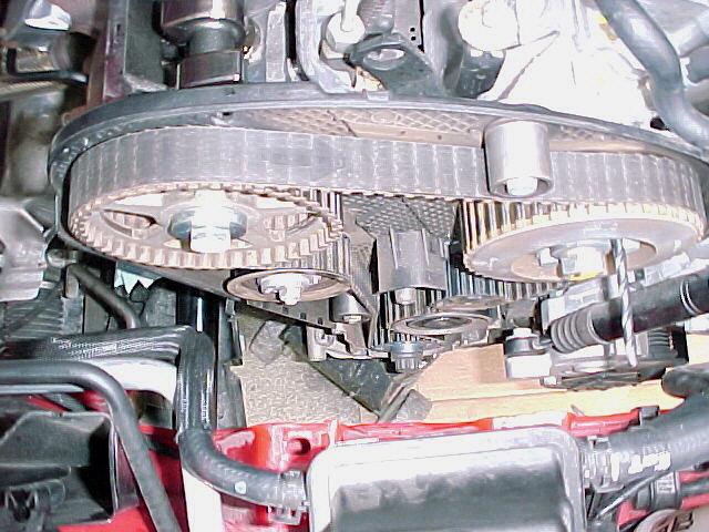
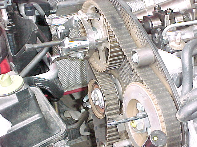
I am too cheap to spend a lot of money on tools I will only use once every two years. I found that a standard three jaw puller will work if some precaution is taken. The puller is installed with only slight tension and then a screw type radiator hose clamp is installed around the puller jaws to keep pressure inward on them so they won't slip out from engagement with the cam pulley hub. It's not a bad fit, in fact I was tempted to try without the clamp but experience has taught me that once something slips, it's harder to keep it from slipping than if it just never slips in the first place. For the injection pump lock I used a #B drill bit. The diameter is .238". The next size up is #C at .242". #C was too big to go into the hole and #B was a tight fit so I figured I couldn't be off more than .004. It worked. Next time I will wrap the flutes with duct tape as they are sharp and can cut.
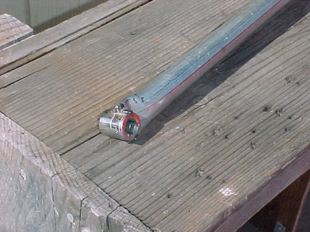
The cam turning tool is made from 3/8 round bar welded to electrical conduit.
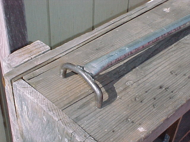
A socket on the other end of the conduit is the serpentine belt tensioner tool.
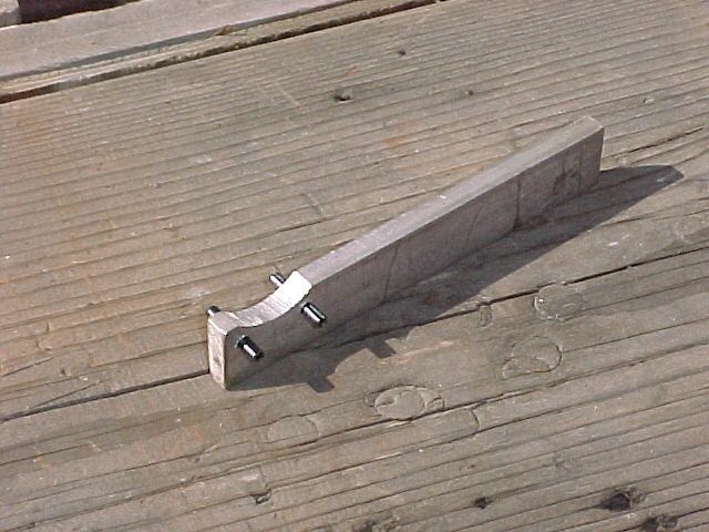
The timing belt tensioner tool is made from aluminum flat bar and 1/8" rolled pins. I found it useable, but with difficulty. I should have used a slightly wider piece of aluminum so both pins could have been positioned at the end of the bar, which would have made it easier to get my hand around.
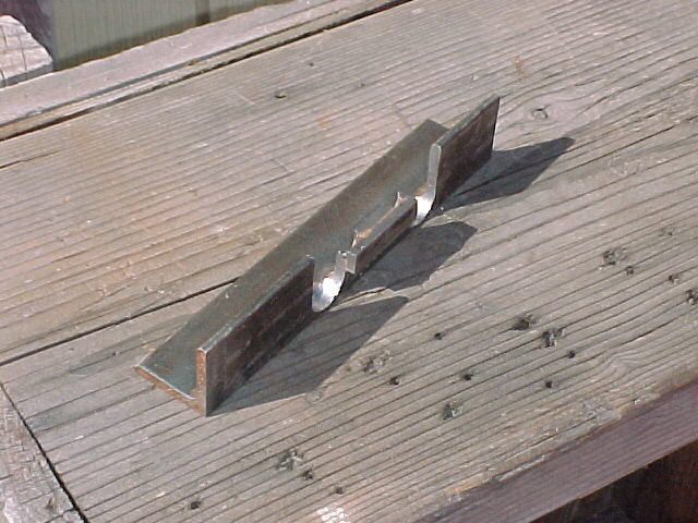
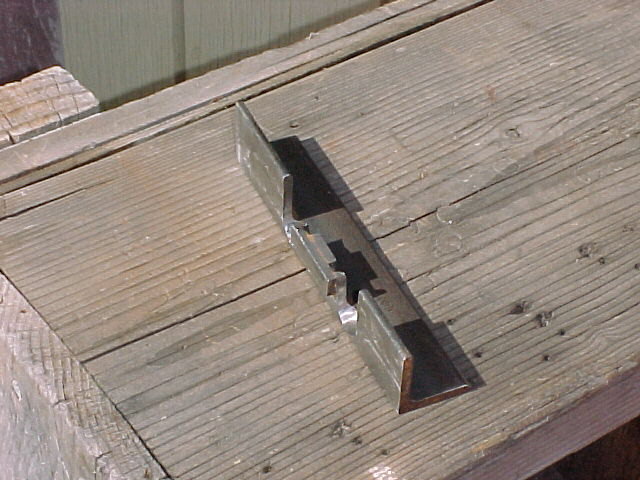
The cam holding bar is made from angle iron. This required a milling machine and some welding to accomplish. It is designed like the A3 bar which needs to be aligned with the top of the head by shimming it with feeler guages. A benefit of this is the ability to alter the cam timing. Each .0035" difference per side is equal to one degree.
Last fiddled with 23 Nov. 01. Click here to go back one page.