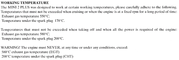
Since there is so little technical information about the Simonini Mini 2 Plus motor on the internet, I thought others might benefit from what I have managed to find out. I'll add to it from time to time. |


|
Kill switch problem
I've had the kill switch fail to stop the motor on more than one occasion after the motor had been running hard. Judging from the response I got from asking about it on the internet groups, many people have this problem with the Simonini. Most just give it some throttle and then the kill switch works.
Causes for this running-on are suggested to be defective switches or defective wiring or some kind of inductance happening in the length of the wires running out to the kill switch in the throttle handle.
I suspected abnormally high combustion temperature to be making some surface within the combustion chamber hot enough to be the source of ignition.
I attached a metal clip between the spark plug and the spark plug wire so it would allow the engine to run normally. Having the metal clip exposed enabled me to short the spark to ground, using an insulated screw driver, while the engine was running. Shorting the spark in this manner, after running the motor hard, would not kill the motor. This confirmed that something in the combustion chamber was getting hot enough to ignite the fuel on it's own. It is decieving because the engine starts well, runs with good power at full throttle and the plug shows a dark cinnamon color. Whatever is causing this is hard on the motor and I didn't want to allow it to continue.
The Simonini manual says not to use fuel with an octane rating less than 98. In US octanes, that would be 95. I've been feeding it the best gas I can find at local stations, which is 91 octane. I'm thinking the engine is detonating at full throttle because of that inferior gas. My goal would be to continue to use the 91 octane gas and find a way to make the motor happy with it.
I purchased and installed Exhaust Gas Temperature and Cylinder Head Temperature gauges and set out to determine how my motor had been running, compared to what my 2004 manual says about engine temperature.
|
|
What I found after about a minute at full throttle was that the CHT was past 450 degrees and the EGT was past 1250 degrees, and both were climbing. I chickened out, without waiting to find out just how hot it was going to get, and closed the throttle.
I suspect my EGT gauge is reading high but I don't know how much. The probe is the hose clamp type and I located it in the best spot with regard to clearing the exhaust spring loops and not being on the taper of the exhaust pipe where it would tend to want to slip from vibration. This works out to be about 5-1/2" from the piston which is on the close side and undoubtedly causing a higher than actual reading.
|
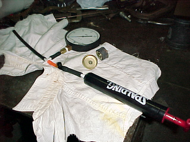
To rule out the possibility of a leaky gasket or crankshaft seal causing a lean condition, the motor was removed from the paramotor frame and pressure tested. The carburetor and exhaust pipe openings were plugged with automotive freeze plugs.
|
|
With the engine pressurized with 5 PSI of air through the carburetor pulse line and soapy water squirted all over the motor I discovered a porous crankcase casting bubbling like crazy.
A few emails to Simonini along with some pictures of the bubbles got a new crankcase to my door in 8 days, no charge as the motor was under warrentee. I had read about Simonini sending a whole motor in this case but in looking back over my emails, I realize that I did not complain about my motor being bad, only that my crankcase was bad. Live and learn. It came with the tools needed to pull the drive pulley and flywheel off the crankshaft, and a new set of gaskets and seals.
Before disassembling the motor, I scribed a mark on the timing plate relative to the retaining bolt, so I could return the timing to where it was before taking the motor apart. The manual makes no mention of setting or checking the timing.
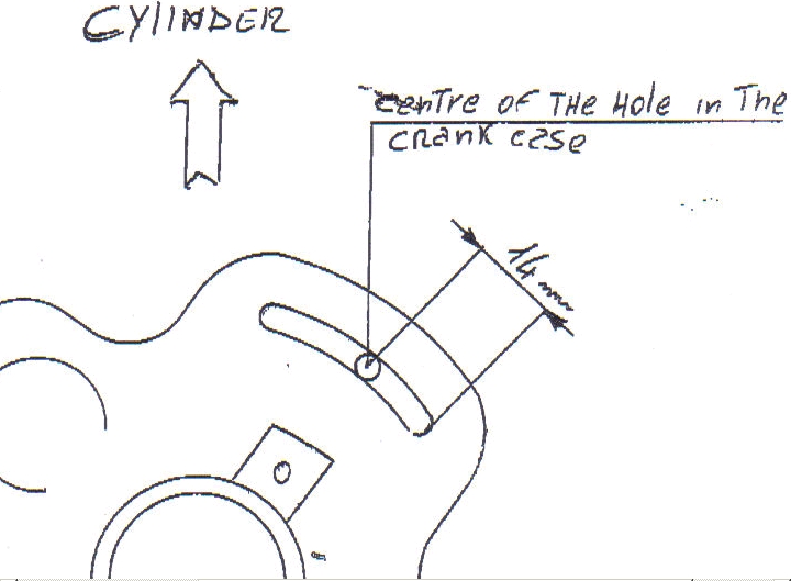
I emailed Simonini asking for information about timing the motor correctly and recieved a fax of what appears to be a tracing of the real timing plate along with the dimension of 14mm called out from the inside end of the slot to the center of the timing plate retaining bolt. Both reference points are machined and so likely to be reliable. |
|
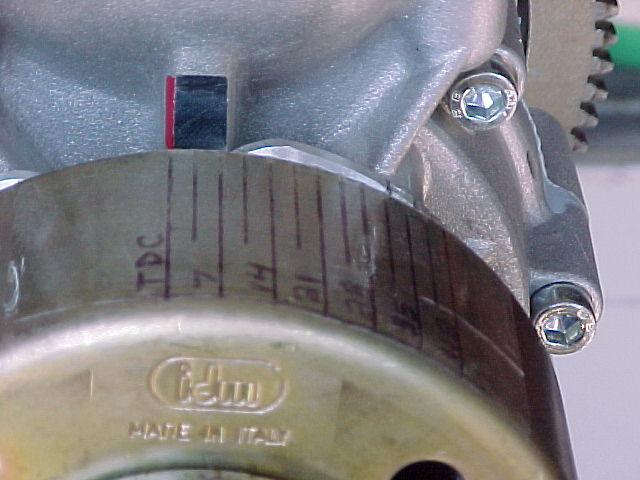
I wanted to know how these measured settings compare with actual Top Dead Center so when I deviate from it while experimenting I'll be able to tell exactly where I'm at. I confirmed that my automotive timing light would work with the Simonini CDI ignition, and then set about to make a degree scale for the flywheel.
|
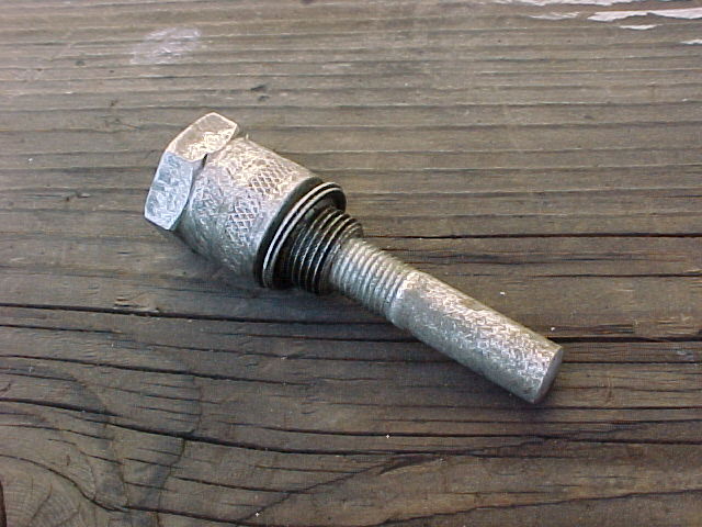
A piston stop tool is necessary for locating Top Dead Center, which must be known in order to properly locate the degree marks on the flywheel. The piston stop was made by removing the porcelain and ground electrode from an old spark plug and threading the hole in the bottom for a 3/8" bolt which I had cut the head off of and smoothed so it wouldn't scratch the piston. The tool is installed into the spark plug hole with the bolt part extending into the cylinder where it stops the pistons upward movement the same distance from the top, when the crankshaft is turned one way and then turned the other by hand. |
|
Turning the flywheel one way and then the other, with the piston stop in place, marks were placed on the flywheel at each stopping point in line with the painted line. TDC was measured and marked exactly half way in between these two stop marks.
|
Next, I measured the circumference of the flywheel and found that, almost exactly, each 1/4" of the flywheel is equal to 7 degrees of crankshaft rotation. I laid some clear tape on a ruler and marked 1/4" spacings in long lines and 1/8" spacings in shorter lines.The long lines were labeled from left to right beginning with TDC and adding 7 degrees to each next one. |
|
From the mark I had scribed prior to disassembling the motor, I was able to duplicate the timing my motor had been running with since brand new, and compare it to the timing as set according to the tracing instructions recently sent to me by Simonini. The original timing was 4 degrees more advanced than that called for in the recently recieved tracing instructions.
While experimenting, I intended to check the timing with the motor being cranked by the electric starter, but I thought it would be a good idea to test it with the motor running to make sure nothing would change when the motor was running. I found out something significant that I have not heard about on the internet or from Simonini.
The stock Simonini CDI ignition has electronic advance built in.
While running, the timing remains the same as it is at cranking speed till about 3500 RPM and then begins climbing untill it levels off 8 degrees more advanced at about 7000 RPM. Maximum advance will always be 8 degrees more than cranking speed advance.
With the spark plug removed so the motor doesn't jiggle so much, the timing is very easy to read at cranking speed.
After setting the timing to where the motor had been running since brand new, I found the original maximum advance was 33 degrees.
No wonder on 91 octane gas the motor internals were getting hot enough to self ignite the fuel, the maximum advance recomended in the tracing instructions recently sent to me, is 29 degrees.
While trying various combinations of carburetor jet adjustment and ignition timing settings I began to see some trends.
At full throttle, advancing the ignition in increments up to 33 degrees brought higher CHT and made the motor sound rumbly, like it was detonating. RPM with a Beres and Hirsch 46X25 was 7600.
Retarding the ignition timing generally lowered the CHT, and made the motor sound much smoother mechanically.
EGT pretty much followed the throttle. At full throttle it was highest at 33 degrees and at 22 degrees and lower in between these two.
At the lower extreme of around 22 degrees timing, a richness level resulting in 4-stroking still would not lower the EGT to safe levels. I didn't explore extreme advanced settings.
As would be expected, rich carb settings lowered both readings, and lean carb settings raised both readings.
Further experimentation is showing that having the timing set at 29 degrees total, as per the recent Simonini tracing instructions, and the high speed jet set to yeild a dark cinnamon plug color, the motor always stops when the kill switch is operated.
This setting however is rich enough to cause a stumble through the mid-range when accelerating from idle to full throttle, regardless of the idle screw setting. CHT runs around 300 degrees and with my EGT probe mounted 5-1/2" from the piston the reading is about 1175 degrees at full throttle. RPM is 7350 with the B&H 46 X 25.
To date, the configuration that seems best with this motor/prop/fuel combination, has with the timing set to 27 degrees full advance, the idle screw at 1/2 turn, the high speed screw at 1-1/2 turn, pop off pressure at 12 PSI and the needle fulcrum .045" below the gasket.
The plug is medium cinnamon in color after a clean chop ending 5 continuous minutes at full throttle. During that run the CHT had stabilized at 325 degrees, this EGT installation reading stabilized at 1150 degrees, and the RPM was 7300. It's runnig Red Line synthetic at 32:1.
The above is with the carburetor throttle plate modified in a manner similar to that which has been suggested by Scott Travers for adapting the carb to this sized motor, and the idle feed delivery ports restricted to reduce mid range fuel flow in a manner similar to that which has been suggested by Alex Varve.

Carburetor Modifications
Modification ideas borrowed from Scott Travers and Alex Varve were applied to the stock Walbro WB 32 carburetor that have helped it to accelerate smoothly through the RPM range and allieviate the mid range richness.
The WB 32 is intended for smaller engines than the Simonini and when mounted on an engine this size, requires the butterfly to be adjusted more open than intended in order to supply the air requirement for idle. By removing the right amount of material from the butterfly, the correct amount of air is allowed to pass through the carburetor when the butterfly is closed and in correct proximity to the idle discharge ports.
With automobile carbs the technique is to drill holes in the butterfly, starting with a small hole and working up to the size that provides enough airflow for the desired idle RPM with the butterfly closed to the proper angle.
Instead of drilling a hole, I followed Scott's lead and removed material from the side of the throttle plate nearest the idle discharge ports. Mine was removed in a straight line with a file so that I could keep track of how much I was removing by measuring the width of the cut each time . The butterfly had to be removed from the carb for each change. |
|
The butterfly retaining screw was hard to thread out the first time because it is deformed at the factory after installation. I had the screw in and out numerous times as I progressively removed more and more material from the plate untill I got the idle speed I wanted with the butterfly closed. Final installation was with thread locking compound on the screw.
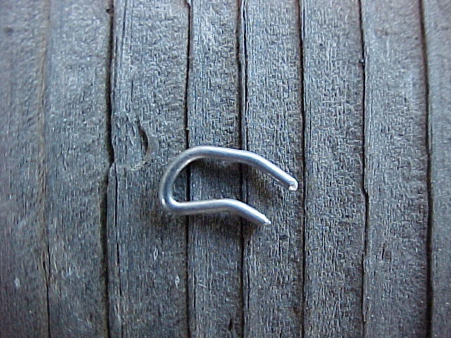
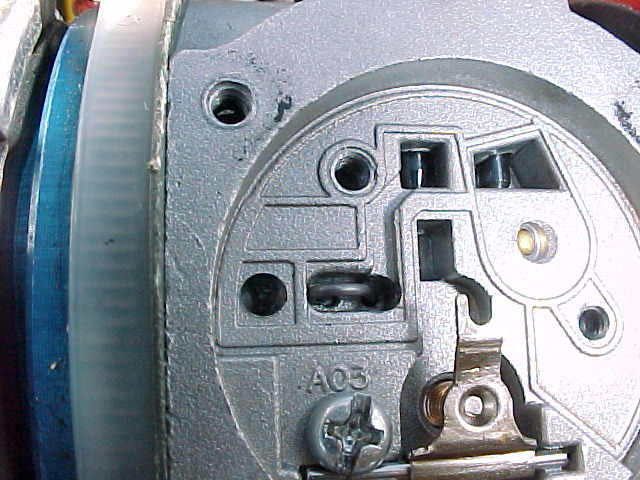
Alex got the mid range richness problem under control by plugging one of the idle discharge ports. I followed that line of thinking, but decided to leave all three idle discharge ports operational and experiment with restricing flow in the two mid range idle discharge ports. A bent "U" shape restrictor was made, using music wire, and the ends were rounded with a fine file. The ends nest into the idle discharge holes in the carb and the restrictor is held in position by the circuit plate. This makes it easy to experiment with different wire sizes.
As it turns out, .032" diameter wire gives clean accelleration through midrange and at a smooth 4800 RPM, EGT runs about 1075 degrees on my guage, and CHT runs about 275 degrees.
|
|
Weight of parts
While I had the motor apart to replace the cracked crankcase casting I weighed the various ignition, starting, and battery charging related parts. I was curious about just how much weight could be saved by removing certain parts.
- ring gear = 13.4 oz.
- flywheel = 28.2 oz.
- stator coil assembly = 16.4 oz.
- Ignition CDI coil = forgot to weigh
- starter = 30.5 oz.
- battery = 51.2 oz.
- wiring and switches = 8.0 oz.
|
|
 |